*** Part 2: The Exchanger and TEC's ***
When you consider the use of TEC's (peltier elements) you need a power source. The more heat you want to move or the greater the temperature change you want requires more power. Since I was dealing with two processors and wanted up to a -40C additional temperature drop, I knew that a typical computer power supply wouldn't cut it. Out come the power supply design handbook and after many trips to Radio Shack, Sandy's Electronics and the local swap meet, I had a 35amp, 15volt, variable power supply.
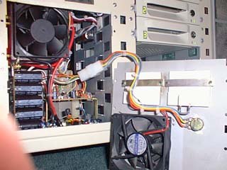
Making it variable would allow me to adjust the capacity of the TEC's to the point they would displace the greatest temperature with the least amount of parasitic heat pumped into the cooling system.
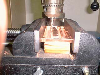
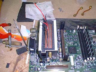
Building the heat exchangers would become a challenge. They had to be rigid in order to ensure a truly flat surface to mount the TEC's. I ordered a piece of 1/4" x 2" x 4' copper bar stock ($32.54). This would become the exchangers and the thermal plates mounted between the processor and TEC's. I cut the bar stock into 4' long pieces, four pieces became the "halves" of the exchanger and two were used as the cold plates. Using a 1/$ "plunge" end mill, I machined out fluid chambers in the copper bar stock as show in the PIC below. The two halve were mirrored and then soldered together with silver solder. I then drilled to .310" holes in the end and tapped them for 1/8" pipe fittings. The fittings you see are 1/8" pipe to 1/8" tubing compression. Using a piece of glass and different grits of wet/dry sand paper, I made sure that the surface of the exchangers were with .005" of flat to mate up to the peltier elements.
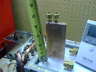
After using the Aztec® program downloaded from Melcor @ http://www.melcor.com, I decided on the CP1.4-127-LH1 peltiers with two mounted in series on each processor. This would give me the ablilty to move 34W of heat with a delta of -40C. Since the peltiers were to be wired in series, it would allow me a extreme range of power control since they would begin to move heat at 2V and would no longer be efficient at 17.7V. These were sandwiched between the exchanger and the thermal plate using Cool-it-Dude thermal grease.
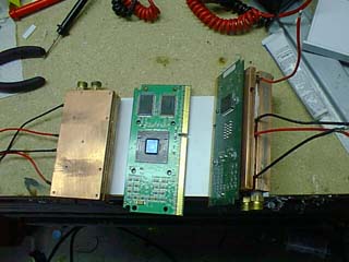
Now that I had the "parts" together, load testing began. I decided to use one of the peltiers to "induce" a 50W load on the thermal plate and just wired up the two others to a standard computer power supply (no control). This resulted in -34.6C.
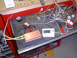
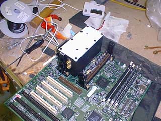
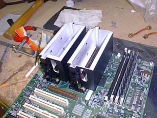
I was now ready to build the insulated enclosures for the processor/exchanger assembly. The testing was exciting in the fact that with a 50 watt load (twice that of the PIII @ 100%), I had achieved -34.6C. With just a little math, -60C was realistic if I could insulate properly and control the condensation. Off to the local hobby shop. I purchased .060, .080 and .120 inch styrene sheet stock to build the enclosures. 3/8" high density foam insulation was also bought from my local A/C shop.
On to Part 3
Back to Home Page