The 100/133Mhz select is handled by A14 on each CPU. According to the Intel spec sheets for the SC242 processors, 100Mhz FSB is selected by ground and 133Mhz FSB is selected by 1K and 3.3K resistor in series. Also the voltage selections are handled by pins A119, B119, A120, & B120 either grounded or open. So the solution.


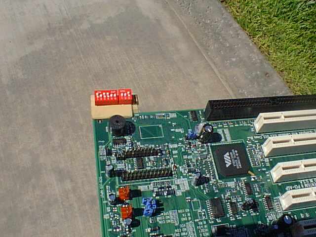
I put together a little circuit board that included 9 DIP switches, 1 for 100/133Mhz FSB control and 8 for Core voltage control. The FSB control switch was tied to A14 on the back of the motherboard. In the On position it was connected to GND. In the off position it was connected to GND through 1K and 3.3K resistor in series. The other eight were attached to A119, A120, B119 & B120 of each slot 1 connector.
The 9 position DIP Switch can be purchased from http://ww.digikey.com , Part No. A5209-ND for $1.68. As an alternative you can purchase a 10 position DIP Switch from http://www.radioshack.com and add one blank row to the PCB.
At PCB etching kit can be purchased from http://www.radioshack.com , Part No. 276-1576 for 13.99. Radioshack.com also carries the 1K Ohm and the 3.3K Ohm 1/4 or 1/2 watt resistors, the 28Ga. Solid insulated wire, solder and soldering irons.
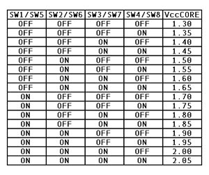
The voltage control is as follows:
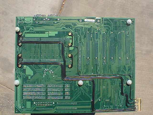
Once I had assembled the circuit board I began the wiring process (28Ga. solid, insulated). Using a VOM I located a good ground connection close to the point I has attached the circuit board to the motherboard (with 5 Min. epoxy). I then soldered the end of a wire to it. Using very small sink tubing, I pushed as close as possible onto the soldered connection. Using "superglue" I routed the wire across the back of the mobo to the new circuit board, attaching it here and there as I bent it around. This is the same process for all the wires, finishing connection of both ends of each wire before moving onto the next wire.
Before you get started soldering wire to the slot1 terminations, carefully verify the pins to the correct designations. Verify A1 on the back and then count off to A14 on each slot...MARK IT. Locating A119,A120, B119and B120 are easier as there is only A121 and B121 after them, just make sure you have the A side and the B side identified correctly. A120 and A119 are the second and third pin from the top of the header array and the same for the B pins.
Check your connections on the A119 to B120 terms to make sure they are not toughing each other or another term next to it. Now that the mobo mods are completed, you have to do a couple of things to the CPU's. Remember the article at Tom's Hardware outlining the "A14" trick, well that’s where we start.

The best way I have found to cover the A14 pin is with regular old Red finger nail polish. Using a tooth pick, you can easily dab it on and it can be removed very easily later. Now you don't stop here, the Coppermine processor grounds A119, A120, B119 and B120 so you need to isolate them too, cover those pins on the CPU. Let them dry for about 30min before you install them in the motherboard.
With this setup now SW9 in the ON position will boot at 100FSB and the OFF position will boot at 133FSB. Start in the OFF position with a 1.95V setting at first to make sure the mobo will post with both processors. If you get into you OS fine and it doesn't crash under load, start reducing the voltage .05V at a time until she won't post or starts crashing under load.
With a little patience really anyone can make this modification and this assures you of a working 133FSB on a "E" (100FSB) Coppermine processor.
Coming is my MSI 694D Pro setup. Today I received my copper water blocks from Danger Den and they are the most impressive units that I have seen. Because of my wild projects, I have received sample of all kinds of units for sale on the internet and until now, they just sit in my shop because they weren't worth the time of day. These are so well constructed, right down to the hold down clip, that I will never have to build a Socket exchanger again. For the price and quality, you would be a moron to buy from anyone else or try to build your own. The a-MAZE-ing Copper Block is the tits-up.
Back to Home Page