My first experience with this motherboard was "What a piece of crap"....(Rev. E) but then I got the Revision F and a glimmer of hope was back for Tyan, whom I have great respect for because of the quality of their products
The TYAN® Tiger 133™ is a Dual Slot 1 motherboard, sporting 6 PCI slots, the minimum that I need for my use in my heavily loaded workstations.
As with any new motherboard, I first checked the TYAN website for any BIOS revisions and found Version 1.05 which I immediately downloaded.
First things first. Now I have been using my 700Mhz Coppermine™ processors at 133Mhz FSB with thermal acceleration for over five months, so I went into the Award BIOS™ to set the FSB at 133Mhz. To my surprise again, there were no Bios overrides for the FSB, in fact no FSB settings in Bios what so ever. I immediately flashed the Bios to the new version 1.05 and tried again. NO FSB SETTINGS IN BIOS. This was the first big disappointment.
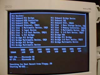
Well out came both processors and the A14 "trick" was applied. (See Tom's Hardware.) This proved to be a worthless attempt on this motherboard, so I began the process of populating the PCI slots with all my hardware. Because the Tiger 133 does not support the Adaptec RaidPort™ SCSI controllers, I elected to use an AMI MegaRaid™ 428 dual channel controller. Because the two AMI raid controller share the Firmware over the PCI bus, slot selection was a problem because the Award Bios of the Tiger seems to "dislike" this arrangement. Finally after placing the AMI 428 in slot one and the AMI 434 in slot 4, I got a full boot.
The idea behind this project was to put together a "over" 1Ghz system using water/peltier cooling that could be built by anyone. One of the first things that control the success of a PIII overclocking project is CPU core voltage control. Also since the A14 "trick" was less than sucessful, another 'mod' would have to be investigated. The 100/133Mhz select is handled by A14 on each CPU. According to the Intel spec sheets for the SC242 processors, 100Mhz FSB is selected by ground and 133Mhz FSB is selected by 1K and 3.3K resistor in series. Also the voltage selections are handled by pins A119, B119, A120, & B120 either grounded or open. So the solution.
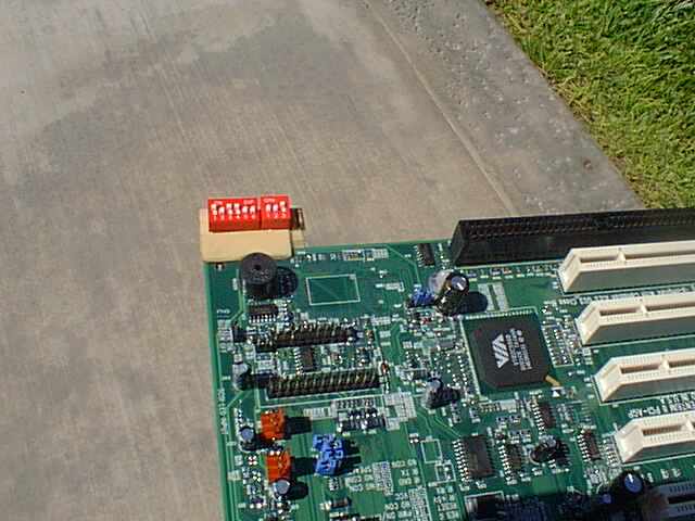
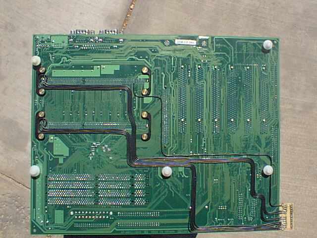
I put together a little circuit board that included 9 DIP switches, 1 for 100/133Mhz FSB control and 8 for Core voltage control. The FSB control switch was tied to A14 on the back of the motherboard. In the On position it was connected to GND. In the off position it was connected to GND through 1K and 3.3K resistor in series. The other eight were attached to A119, A120, B119 & B120 of each slot 1 connector.
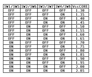
The voltage control is as follows:
The next process was to get the over 1Ghz threshhold. Since the idea was a "Turn it on and GO" approach, I elected to use PIII 800E because of there 8.0 multiplier, 133FSB x 8.0 = 1067Mhz.
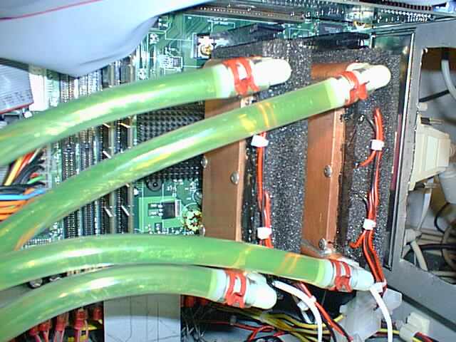
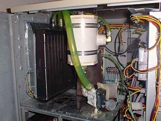
Now remember that anyone can take a motherboard that is manufactured specifically for overclockers, slap a video card and IDE drive on it and crank up the speed of the processor long enough to run some benches, but really, is this a working computer system. The test is building a real work horse that will be rock stable and can actually be used for some real projects. The test system can be seen here.
I have used many 'Supercoolin" solutions, but again the idea here was a system that you could build at home with common tools. Now I have worked with many water solutions in aluminum and copper and found that the copper is the only real solution, but building a great copper exchanger is difficult. So this was my solution:
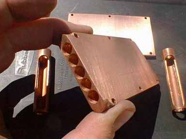

For complete details GOTO Copper Exchanger
With aluminum I could get -8C at idle in NT4.0 and under full load +15C, not exactly safe for a PIII 800E running at 1067Mhz. With the copper exchangers and the same peltiers, it now runs a -19.7C at idle and -4.6C to -2.8C under full load and 1.95V core settings. With the 1.95V core voltage I have posted everytime I turn the computer on and by the time NT starts loading the system the processors have dropped to below 0C.
The system has now run seven days continuous with two command line version of Seti@Home running in the background and then running some 3D animations, a DVD movie, Outlook and Explorer, and capturing the DVD to disk at the same time.


Disappointment three came when I tried to "tweak" the memory settings as described at VIAHardware. With one memory module in, the tweaks were possible, with 4 memory modules in, lock-up, lock-up, lock-up, lock-up and on and on. I have tried three different memory manufactuers, all with the same results. If anyone has any suggestions on this problem, e-mail me below.

Well other than the memory performance, the system is lighting fast and rock stable, and compared to a dual PIII 1Ghz which cannot be air cooled to a stable system and will cost over $2,500.00 to build bare bones, this solution costs less than $2,000.00 bare bones (mobo, processors, cooling system, case, peltier power supply) and Kicks Ass!!!!
Now hopefully Tyan will update their BIOS to include some memory interleave settings and maybe some FSB control but it is not likely since this is a limited life mobo with the slot 1 CPU's being pull out of production in the next six to eight months.
Back to Home Page