The condenser is probably the one thing that will make or break a good Phase Change Cooling system. As discussed on the prior page, I started with a big junk evaporator coil that I picked up from a local commercial A/C contractor. Taking the Dremel tool with a cut off wheel, I cut out the size that I needed.
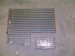
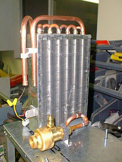
At one end is the open end from the "cut-off" and the other end is the bends of tubing. First I removed enough of the aluminum fin material to expose the copper tubing. The with a butane torch, I removed the 180° copper ends from the side that had them soldered in from the factory. Now remember that the tubing in the coil is smaller I.D. than the 180° ends. You have to "swedge" the open ends. I did this by taking incremental sizes of drill bits and "working" them into the copper tubing to increase the I.D.
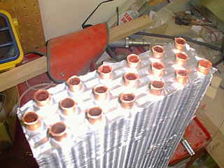
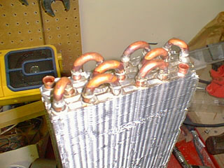
Now that all the 180° bends fit into the tubing, Silver solder flux was wiped on both the bends and the tubing and silver soldered into place.
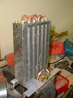
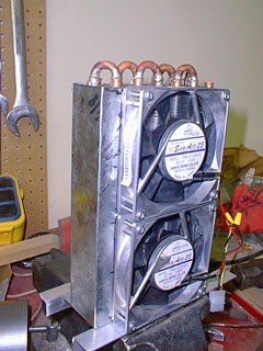
28ga. Sheet metal was used to form the sides and face of the coil and then two 120MM, 115CFM, 12V fans were just sheet metal screwed into place.
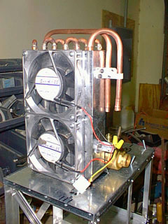
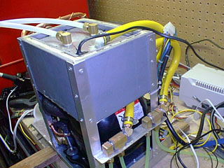
The condenser coil was then mounted to a 20ga. Base that would hold the whole system. Inlet and outlet tubing was added to prepare the hook up to the mini receiver/dryer and the compressor outlet. In these pictures, as well as the cover page, I used a "hot-bypass" valve. Further evolution of the system found that this was not need and was removed, saving on costs, adjustments, and plumbing difficulties.
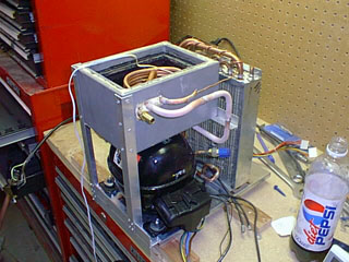
The long copper bulb you see in the picture above is the mini receiver/dryer. Inside this is the drying compound and soldered in the top, is a pressure switch and the capillary tubing. This part can be picked up at any local a/c or refrigeration repair/supply store. The purpose of the pressure switch is to prevent the fans on the condenser from coming on until the compressor has reached working pressure on the high side. The capillary tubing was wrapped around the inlet side tubing to keep it from "icing" up since the tiny tubing is hard to insulate. The capillary tubing is run into the inlet side of the evaporator coil and soldered up.
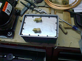
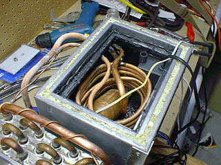
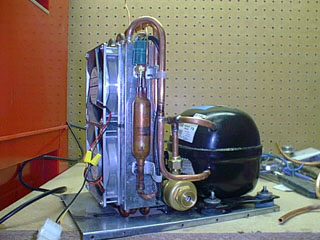
The coolant container was fabricated out of 20ga. Sheet metal with all the side soldered together. In order to make and attach the lid of the tank, I soldered a 3/16" x 3/16" "L" made out of 20ga. material inside the tank. First I cut the lid out of 1/8" aluminum plate and then drilled holes around the edge for the attachment screws. Then with #6x32 allen head screws and #6x32 nuts I attached the "L" metal to the lid and soldered the nuts to the "L' metal pieces. These were then soldered to the inside of the tank. Even though the soldered up tank was sealed with the solder, I still wanted that "extra" protection. I went to HomeDepo® and bought two cans of liquid electrical tape. With this I lined the inside of the tank. Next step was to make a permanent gasket for the lid. After a few tries with a old cut up inner tube and some other different rubber, I decided to make it out of silicone. I went to AutoZone® and bought a tube of Ultra-Black 3M gasket silicone and put a thick bead on the "L" metal edge, meanwhile I had coated the lid with Vaseline petroleum jelly, along with the allen head screws. The lid was placed lightly on the silicone and the screws were started in the threads of the nuts that had been soldered to the "L" metal. I waited overnight for the silicone to dry and then removed the screws and lifted the lid off. What was left was a perfectly formed, pliable gasket that was permanent. The evaporator was made out of 1/8" tubing just "coiled" in a circle. In the one picture you see a large copper bulb. This is the accumulator. It serves the purpose of holding an amount of liquid freon just before the compressor inlet and helps the process of converting the gaseous freon back to liquid before it re-enters the compressor. In this picture, I had installed it in the tank. I future systems it was installed outside the tank and insulated. This was found to be much more efficient and dropped the coolant temp another -5C. The new accumulators that I use are made out of a 6" piece of 2" O.D. copper tubing with standard 2" copper end caps soldered on it. You then drill holes in the to and bottom to run one line in the top from the evaporator and one line in the bottom for the compressor inlet. The two brass fitting you see in the top of the lid are for filling the tank with the coolant.
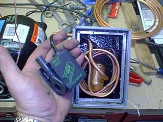
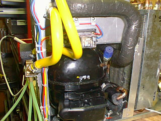
Hole were drilled in the side of the tank for the evaporator inlet and outlet along with the coolant return, and once the evaporator and return tubing were installed inside the tank, they were sealed with silicone to prevent leaks. Additional holes were drilled in the lid for the pump outlet and the power cord for the pump. These were seal with 5-min epoxy as the pump had to be removed with the lid. The yellow rubber tubing supplies the chilled water to the brass manifolds than feed the exchangers. All exposed "cold" tubing was then wrapped with insulation. The DPDT, 12V Coil relay attached to the side of the tank is used to "turn-on" the power to the compressor and fans when power was applied to the computer.
Now all you have to do is take it to a local auto shop, have them evacuate the system, check it for leaks, take your R-134a fill kit you bought from AutoZone® and fill it up.
Back to Home Page